
Maximite FAQ
![]()
![]()
Features and Capabilities
Will you implement Ethernet and/or WiFi on the Maximite?
Theoretically it is possible to add both, although at this time only a WiFi capability is being considered.
Does the Maximite have a RTC (real time clock) to keep track of the time?
Yes, it does. The TIME$ function tracks time and the DATE$ function will track the date including allowance for leap years, etc. The Colour Maximite with the battery backed clock will automatically track the correct time even when powered off. For the other Maximites the clock will be reset to zero on power up.
Can I get data from a GPS module?
Yes, no problem. The MMBasic Library has a short program called GPS.BAS that shows how to get the latitude, longitude, speed, super accurate time of day and more from a GPS module.
Can I call assembly language subroutines or run non BASIC programs?
This feature was included in the early computers like the Tandy so that users could write fast subroutines or access hidden features of the computer. In the case of the Maximite the main issue would be learning to program in MIPS assembler - the early computers used simple 8 bit CPUs while the Maximite has a 32 bit CPU designed for optimising compilers and that is much, much harder to deal with. Also, you do not have to do it! The C source code to the Maximite (including MMBasic) and the complete development environment is free to download and use. You can add your own functions to MMBasic, recompile it and re flash the chip (a programmer is not required). Much easier than writing in MIPS assembler.
Can I program the Maximite in C?
Yes. All you need is MPLAB and the free C32 compiler from Microchip. Get the source code from http://mmbasic.com and add whatever you need. You can even completely remove the MMBasic language component and replace it with your own code while still using features like the VGA output and keyboard. It is also easy to use the Maximite hardware for other applications. For example, there is the RetroBSD project which has UNIX running on the Maximite.
BUT, if you want to use the interpretive "type-a-command-in-and-see-the-result" style like BASIC then sorry, the C language does not easily lend itself to that type of use (it expects a compiler).
Will parallel or USB printer support be available on the Maximite in the future?
At this time there are no plans to add a parallel printer port. Although it could be done it would not help because parallel printers are very hard to find these days. USB printer support would be much better but it cannot be done because the Maximite USB port is a device only, not a host which is what would be required to support a USB printer.
Do the mini and micro sizes of SDHC cards work OK with an adapter?
Yes, cards up to 64GB (formatted as FAT32) have been tested and work fine.
Can you change the VGA resolution to 640x480 (or some other resolution)?
No, the current resolution is fixed by the PIC32 hardware, it is not a design decision. Video is generated by (mis)using the SPI interface on the PIC32 chip and that is limited in the clock speeds that it can use - and that in turn determines the number of pixels on the screen. Remember, the whole Maximite is contained in a single chip costing under $10, it is amazing that it can be coaxed into generating VGA video in the first place.
The circles drawn on the video display are not perfectly round, can you fix that?
The way that the video is generated (see the previous answer) forces us to use slightly rectangular pixels and that is why the circles are not perfectly round. In version MMBasic 4.3A and later you can specify the aspect ratio of a circle and using that feature you can get a perfectly round circle.
Can I peek and poke video memory directly? If yes, where is it located and is there a memory map?
Yes, using the PEEK and POKE commands you can access the buffer in RAM. In MMBasic 4.0 and later you can use the keyword VIDEO on the monochrome Maximite or RVIDEO, GVIDEO, BVIDEO (red, blue and green video buffers) on the Colour Maximite.
Is there any way to define a constant in MMBasic that cannot be accidentally changed in the program?
No, at this time there is no way to define a constant. It would be a good feature to have, perhaps in a future version.
It is possible for video updates to be synchronised to the vertical sync? Vintage computers used this technique to avoid flicker on the video output.
MMBasic does not need to do this because the firmware can write to the video RAM at the same time as it is being used to generate the video. Older systems could not do that which meant that when the CPU wrote to the RAM the video was momentarily blanked, which caused flicker.
Try running the following short program and you will not see any flicker, even though the video RAM is constantly being updated while generating the video:
CLS
DO
PRINT @(100,100) "Hello World"
LOOP
The Colour Maximite
Can I modify my original monochrome Maximite to generate colour?
Yes you can but it is not straight forward. You need to remove the VGA connector (difficult because the board has plated through holes), cut some tracks and add some jumper leads (see this post for an example). This is not easy and there are other issues, for example using the SD card causes interference on the video screen (more details can be found on this web page).
Because of these issues the current version of MMBasic does not support colour on a modified monochrome Maximite.
Can you use colour coding for MMBasic keywords in the full screen editor?
No. The reason is that the editor switches the Colour Maximite into monochrome mode to get the maximum amount of free memory while it is running. It then switches back to the original mode when it exits. In monochrome mode only one colour is possible (the editor uses the foreground colour selected by the COLOUR command).
If are you wondering how the editor then manages to use colour for the status line check the SCANLINE command.
Is the composite video output in colour? Will it ever be so in the future?
The composite output is monochrome. Generating the colour burst and the required integrated video is far beyond the capabilities of the PIC32 so it is not a future possibility.
You can get colour composite using an adapter as described in this forum discussion.
Why must MOD files be copied to drive A:? Why not play them from the SD card?
When the synthesiser plays a MOD file it must jump around at high speed in the file reading different sections and accessing the file on the SD card would be too slow. When the file is copied to drive A: it is programmed into the flash memory of the PIC32 where access is instantaneous.
Another option would have been to copy the file to RAM and play it from there but that would consume too much RAM leaving almost nothing for programs. So, the solution is to play the file from drive A:.
Hardware and Construction
The Colour Maximite will not work with some VGA monitors.
The Colour Maximite uses pin 9 on the VGA connector to switch to composite video timing, unfortunately some VGA monitors (predominately HP monitors) ground that pin and so the Maximite is forced into composite video when such a monitor is attached. The solution is to upgrade to the latest version of MMBasic which, by default, disables composite video. See the Maximite Hardware Manual for details of how to enable composite video if it is needed.
The power LED does not light and the Maximite draws very little current (normal consumption is 125mA).
The capacitor connected to the Vcap pin of the PIC32 (C10 in the Colour Maximite, C5 in the Maximite and C3 in the mini Maximite) is nearly always responsible. It must be a low ESR Tantalum capacitor or a 10uF ceramic SMD capacitor between the solder pads for C5 (or C3). The best fix is to use a 10μF 16V Ceramic with a X5R dielectric. For example, Element14 1845747. It never fails.
The Maximite will reset when I start a motor or fluorescent light.
The Maximite just intermittently stops running or resets.
This is also caused the capacitor connected to the Vcap pin of the PIC32. See the above answer.
Serial over USB will not work or causes errors but the bootloader works fine.
Using USB power as the power source is probably the cause of this. Other symptoms include the Maximite will not start up, random errors using the USB, errors writing to the SD card, and similar. Many computers or hubs cannot supply a clean power supply so try an external 9V to 12V power pack (wall wart).
Cannot recognise some SD cards or errors when reading or writing to them.
For the Original (monochrome) Maximite this was an issue with the earlier versions of MMBasic and is fixed in the current version. For the Colour Maximite this might be caused by noise appearing on the 2.2 ohm resistor. Try a 10µF tantalum or ceramic capacitor from pin 4 of the SD card connector (Vdd) to ground (Vss).
The Maximite resets when an SD card is inserted.
This is due to the sudden load of the SD card causing a glitch on the 3.3V supply rail. The solution is to use a different SD card or solder a 22uF low ESR Tantalum capacitor across the supply rails very close to the SD card connector pins. The Colour Maximite has a 2.2 ohm resistor in series with the supply rail to the SD card to prevent this effect. If you have an issue with a card on the Colour Maximite increase the value of this resistor.
Error when writing to the internal flash drive A:
This is caused by the 3.3V power to the PIC32 being too low. When writing to the flash memory the supply to the chip must be at least 2.9V.
I think that I have accidentally damaged the PIC32 chip
The PIC32 chip seems to be running very hot and might be damaged.
It is very unlikely that you have destroyed the PIC32 chip as it is very tough and it normally runs quite hot anyway. Before blaming the chip check your soldering, the capacitor connected to the Vcap pin of the PIC32 and use an external power supply. If you are really convinced that your chip is dead you can purchase a pre programmed replacement from Silicon Chip magazine for $15.
The left hand character of each line is missing. This only happened after I upgraded my Altronics kit to the latest version of MMBasic.
This is easy. At version 2.6 the timing of the VGA output was altered slightly to correct another issue. This had the effect of shifting the entire screen left by eight pixels compared to earlier versions. To fix your problem all you need to do is adjust the horizontal positioning on your monitor to bring the missing pixels back into view.
The characters are not very clear on my LCD screen.
This is caused by the fact that the number of horizontal pixels generated by the Maximite do not exactly match the number of pixels in your LCD screen. The LCD will try and compensate for this but some screens do not do it very well. The old analog (CRT) monitors did not have this problem and they always generate a sharp picture. On the Colour Maximite this effect can cause some colour fringing on white text or graphics.
I have just bought a stock UBW32 and the 1.6.3 firmware has loaded and runs fine. I loaded MMBasic and my Windows PC refuses to see the board.
Probably you have not loaded the correct USB serial port driver. MMBasic on the UBW32 uses a different driver to the firmware originally supplied with the UBW32. Download and install the "Silicon Chip USB Serial Driver" from the downloads section.
Cannot use the serial over USB feature on the DuinoMite MMBasic.
This is similar to the UBW32 question above. MMBasic uses the "Silicon Chip USB Serial Driver" which is the standard for all Maximite versions of MMBasic. This driver can be downloaded from the downloads section. Note that the Olimex modified version of MMBasic (originally supplied on the DuinoMite) uses a different driver that can be downloaded from Olimex.
I cannot get the COM serial ports to work with RS323 - I get random characters or nothing at all.
MMBasic supports a TTL level serial interface which uses 0 to 5V for signaling. This is different to RS232 which uses ±12V signaling levels that are inverted compared to the TTL levels. To connect to an RS232 interface (as found on a PC) you need a converter chip like the MAX232. Another possibility is this USB converter which is ideal for interfacing to PCs.
I installed the components for the battery backed clock on the Colour Maximite but MMBasic does not prompt to set the time as described in the manual. It acts as if the clock components are not installed.
Have you installed the battery? Without a battery the DS1703 will not work, even when power is applied. This causes MMBasic to believe that the clock is not installed.
The battery backed clock on the Colour Maximite is recognised by MMBasic and I can set the time but when I reboot the time reverts to the time originally set. It as if the clock is not advancing the time.
Something is wrong with the 32KHz watch crystal. Check the soldering around the crystal and if that looks OK replace the crystal. They are fragile but they are cheap and can be bought from any electronic components supplier or salvaged from an old wall clock or watch.
On the Colour Maximite some white letters have a slightly coloured fringe. Why is this?
This is unavoidable and is caused by the fact that the SPI channels (which generate the video for each colour) may not start at exactly the same time. This is made worse by LCD monitors which need to upscale the video to their pixel density. If it occurs, the effect will vary from monitor to monitor and does not show at all on the old fashioned CRT monitors.
Using the Maximite and MMBasic
How do I enter programs that do not use line numbers?
When I type in a program line without a line number it is executed immediately and not saved in memory.
This is the old way that BASIC interpreters work and MMBasic is fully compatible with this convention. If you want to enter a program without line numbers use the AUTO or EDIT commands.
I cannot get the serial over USB feature to work.
It does work and thousands of people have it running on Windows, the Mac and Linux. For Windows you must install the device driver and exactly follow each step in the notes provided with the driver. Most problems are caused by skipping or modifying a step. For Windows 8 the operating system must be instructed to load uncertified drivers (instructions are included with the latest version of the driver). For Mac users there are notes in the download section of the main Maximite web page.
If I copy and paste text into Terra Term MMBasic looses a lot of the text.
You need to set a delay in Terra Term so that it does not overwhelm the USB interface. Go to Setup -> Serial Port and set the Transmit delay to 50 msec/line. Don't set a delay per character as that will prevent the proper decoding of function keys.
I set Terra Term to have a delay of 50 msec/line but it still looses characters when I paste text into the full screen editor.
The editor has a lot of work to do when each character is entered and it cannot service the USB interface fast enough when copy and paste is used. The best way to paste a lot of text is with the AUTO command. If you use AUTO without any arguments it will just take text from the input and append it to program memory, you terminate the command with a CTRL-C. This is very fast and does not loose any text.
Occasionally the cursor looses its place in the full screen editor compared to where new text is inserted.
If ever the full screen editor gets confused just hit HOME twice. That will go to the top of the file, redraw the screen and reset the internal pointers that are used to track the cursor position.
If I press F1 in the full screen editor editor to save the changes the prompt appears but the changes are not saved to the SD card. I had to type in SAVE at the prompt.
Yes, that is correct. If you just used the command EDIT (without a file name) then you will edit the program in memory and that is where your edits will be saved when you press F1 to save. If you used a file name with the edit command (ie, EDIT "FOO.BAS") then you will edit the file on the SD card and that is where the file will be saved when you press F1. This is documented in the User Manual (admittedly briefly).
When using serial terminal mode over USB the backspace key does not work.
It does work. Probably you are using PuTTY as the terminal emulator and you have not configured it to send the backspace code when pressing backspace.
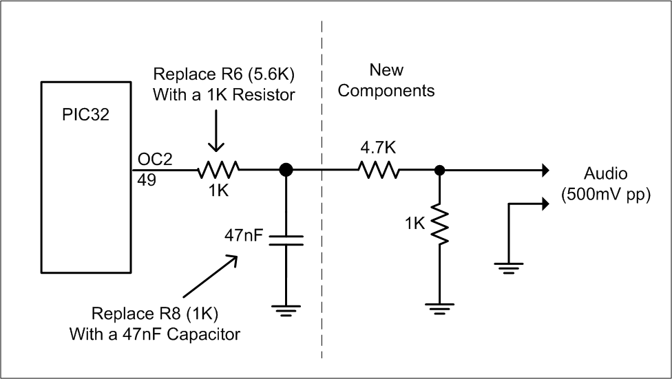
When using the PLAYMOD and TONE commands on my monochrome Maximite I get a square wave output that my amplifier does not like.
You need to replace the components on the sound output with a low pass filter. This diagram shows what is needed.
Refer to the Colour Maximite Design and Construction page for an explanation of the low pass filter and more details on on the audio output.
General
How on earth did MMBasic get written in a couple weeks, it is too complex?
The couple of weeks was for the core of the BASIC language, there has been a lot of work since adding things like the communications protocols. By now over 12 months has been spent on the project.
Where did you get the patch leads shown in the photo of the Maximite wired to a breadboard?
The leads that I use are 12cm long and have a male pin at one end and a female socket at the other. Mine came from SchmartBoard.com (part 920-0023-01) but you can also buy similar ones from SparkFun.com or make up your own using a female socket (Jaycar HP1260) and pins taken from a header strip (Jaycar HM3211).