
The mini Maximite
![]()
![]()
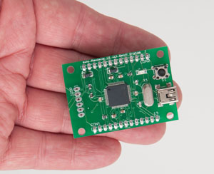 The mini Maximite is a small low cost version of the popular Maximite computer.
The idea behind it is simple. Physically shrink the Maximite down to the size of a large postage stamp while keeping it fully compatible with the larger version in its external I/O capabilities and programming language.
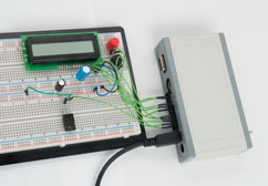
The mini Maximite is designed for use as an intelligent controller to plug into your creation. Because it is 100% software compatible with the larger version you can develop and test your program on the full sized Maximite and transfer it to this miniaturised version when you are ready to screw the covers down.
The mini Maximite was described in the November 2011 issue of Silicon Chip magazine. This page is intended to provide guidance to potential constructors and compliments the magazine article. You can purchase back copies of the magazine from the publisher at a modest cost (use this link to request details). You can buy the PCB and programmed chip from Silicon Chip (details below) and source the other components yourself.
Other useful information can be found on these pages:
The rest of this web page assumes a passing familiarity with the original (full sized Maximite). If you don't know anything about that device it would be helpful if you explored the pages describing it starting with the Maximite Home Page.
The Circuit
The mini Maximite is about as simple as it gets... one chip, four resistors and ten capacitors.
Click on the diagram for a larger image.

CON5 is the connector carrying the signals for the missing video, sound and keyboard connectors. CON6 carries the signals for the SD card socket. Both of these connectors would not normally be used in an embedded computer and they can be cut off leaving a small and neat small PCB.
D1 is the "power LED". MMBasic turns it on after it has initialised everything so this makes a good test - if the light is on, you are OK. If not, you have a problem.
CON1 and CON2 are the external I/O connectors carrying 20 signal lines which can be inputs, outputs, counting inputs, etc. The layout matches the full sized Maximite so with a conversion cable you can plug in circuits that were designed to be controlled by the larger Maximite.
CON3 is the ICSP programming connector. You will need this to program the chip if you have purchased a virgin (ie, blank chip). If you have purchased the chip from Silicon Chip (see below) you will not have to bother with this as they will deliver the chip fully programmed.
 SW1 is the bootload button. If you hold it down while you apply power the PIC32 will startup in bootload mode and flash the power light. All firmware updates will come with a Windows application which you can use to reprogram the chip with new firmware over USB. These updates will be made available on the main Maximite page.
X1 is the crystal used for all signal timing, it is multiplied within the PIC32 to give an 80MHz clock. Above the crystal is CON4 which is the USB connector. The PIC32 monitors pin 1 on the USB connector and if it detects +5V it will enable USB communications.
Finally the capacitors along the top of the circuit provide noise suppression and are critical - if the chip will not start (ie, the power LED is not illuminated) you should check these capacitors which could be the wrong type or missing. C3 in particular is critical, it must be a low ESR 22uF Tantalum or 10uF ceramic.
Construction
The first step is to download the mini Maximite Construction Pack at the bottom of this page. It contains all you need to build the mini Maximite including the circuit, parts list, PCB layouts, etc. You can make your own board or send the Gerbers to a PCB fabricator who will make it for you. The blank PIC32 chip can be purchased from microchip.com or futurlec.com. All the other parts are generic and can be source from many suppliers.
A better (and cheaper solution) is to buy the PCB board and PIC32 chip from Silicon Chip magazine (http://www.siliconchip.com.au). The chip supplied by Silicon Chip is pre programmed with MMBasic so you do not need a programmer and subsequent updates are done via a Windows computer and USB.
The parts you need to order are:
Construction takes less than an hour and don't be put off by soldering surface mounted devices, it is easy, see my web page Surface Mount is Easy.
Maximite and MMBasic Support
The main Maximite web page lists the support options and resources for all Maximite versions including the mini Maximite.
Using the mini Maximite
A feature of MMBasic is that it creates a virtual SD card using the flash memory of the PIC32. This means that you can store your program there and you do not need an external SD card for storage. In an embedded situation you normally would also not need the video or keyboard and in that case you can cut the PCB on the dotted line to make a much smaller package.
The following diagram provides a reference list of all the pins on the mini Maximite.
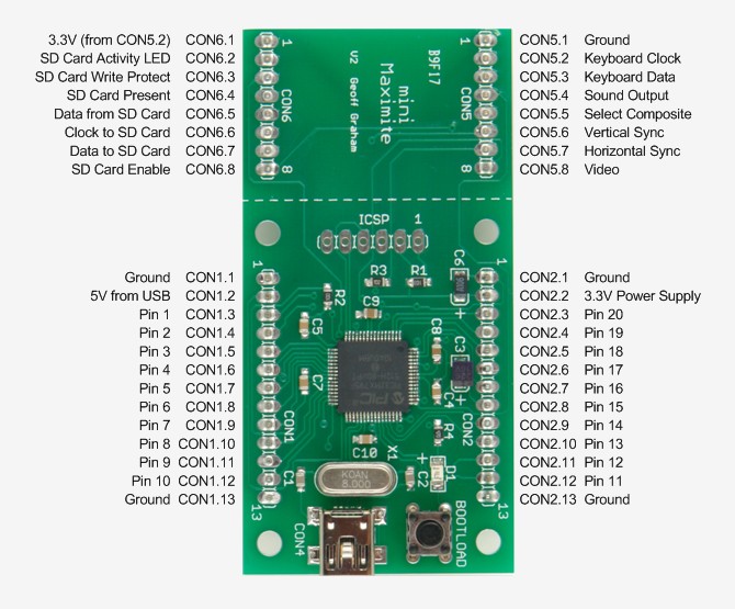 The diagrams for connecting the video, keyboard sound and SD card connectors are available for download at the bottom of this page. The above diagram is also reproduced in the Maximite User Manual which is included with the latest version of Maximite MMBasic (available from here).
There are just a couple things to note when connecting up the mini Maximite.
- CON2 pin 1 is the ground.
- CON2 pin 2 is the power supply. The mini Maximite needs between 2.3 and 3.6V to operate and it draws about 125mA unloaded. When writing to the internal flash memory (drive A: in MMBasic) it needs a minimum of 2.9V.
- CON1 pin 2 is the 5V supply from the USB if it is connected to a host computer. If you want to use this to power the mini Maximite you will have to provide an external low dropout 3.3V regulator and feed its output to CON2 pin 2.
Remember, the mini Maximite is intended to to be mounted inside something rather than being treated as a computer in its own right.
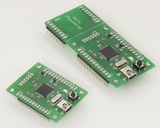
 |
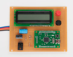
You can develop and test your program on the full sized Maximite (left). And transfer it to the mini Maximite when you are ready to build the final circuit (right). |
 |
| mini Maximite Construction Pack | DOWNLOAD |
| Video, keyboard, sound and SD card connections to the mini Maximite | DOWNLOAD |
For details of all Maximites go to the main Maximite page. Other useful pages are:
- MMBasic introduction
- The MMBasic home page at http://mmbasic.com
- Firmware downloads
- Frequently Asked Questions
- The Maximite Story (how it came about)