SG12232A LCD Display Driver
![]()
![]()
 For some strange reason the suppliers of LCD displays provide terrible documentation for their products. This can turn using one of these otherwise excellent devices into a tedious exercise as you guess how to make the thing work.
This section provides documentation for the SG12232A graphic LCD display and presents driver software that can be incorporated in a microcontroller project.
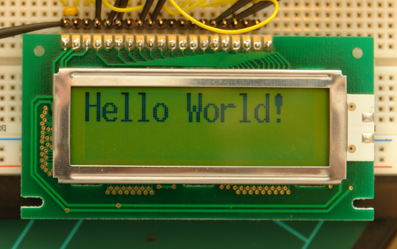
This display is a monochrome 122 x 32 pixel display with a backlight. In Australia the retailer is Altronics (altronics.com.au) who sell it as "Dotmatrix LCD 132 x 32 Backlit" part number Z7052. Note that despite the title, it is only 122 pixels wide.
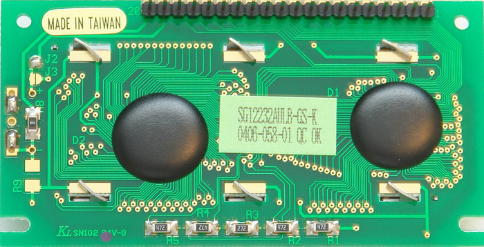
It is also sold under the part number SG12232AULB-GS-K and is part of the "Sunlike Display" series from Global Elecom Corp. The display uses the SED1520 controller chip from S-MOS Systems Inc so you might find this section useful if you have a different display using that chip.
Documentation
Altronics provide the most minimal documentation in a short datasheet. However, a more helpful user manual is available from the download section at the bottom of this page.
 If you want to delve into the details of the SED1520 controller chip, you can also find its data in the download section.
This discussion will not repeat any of this documentation. However, it will try to illuminate some of the obscure aspects not properly covered.
Usage
The LCD communicates over an 8 bit bus and you have four types of communication:
- Reading the status
- Writing a command
- Reading a byte from the buffer memory
- Writing a byte to the buffer memory
Reading and writing is selected by the R/W pin. Accessing the buffer memory or status/command is controlled by the Ao pin. The following table lists the signals and their function. They are all outputs from the microcontroller to the LCD, with the only exception being the data bus which is an input when R/W is high.
| Vss and Vdd | Supply voltage of +5V (Vdd is positive) |
| CL | Clock input. Annoyingly this display requires a square wave signal to make the LCD glass work. The frequency can be anywhere between 3KHz and 50KHz with 4KHz seemingly the optimum. |
| Vo | LCD Glass voltage. This is a negative voltage with respect to the supply voltage (Vdd) and should be about 4.9V negative. Varying this voltage changes the contrast. With a 5V or greater supply this can be provided by a 20K potentiometer between Vdd and Vss with the wiper going to Vo, But, to get full control you need to take Vo greater than 5V negative and that will require generating a voltage that is negative with respect to ground (Vss). |
| Ao | Controls reading/writing to the buffer memory (when Ao is high), or the control/status register (when Ao is low). Should be called D/I (Data/Instruction) as in other graphics displays. |
| CS1 and CS2 | Selects which chipset the command/data is directed to. The signal is active high. For example, if CS2 is high then any command/data is directed to the second chip. |
| E | Enable. This is the data strobe for reading/writing on the bus, it is active high. When writing to the LCD you must have your data on the bus before you take E high and you must keep it there until after you lower it. When reading, the LCD will place its data on the bus about 100nS after E going high. |
| R/W | Read/Write. When high the LCD module will take control of the bus and place its data on it. When low you have control of the bus and can place data on it. Obviously you must also change the direction of the I/O port on your microcontroller when you manipulate R/W. |
| DB0 to DB7 | Data bus |
| RES | Reset signal, pulling it low holds the LCD in reset. Can be permanently wired to +5V |
| A and K | Power to the backlight (A is positive). Do not connect to +5V, use a resistor to limit the current. |
The pin numbers for these signals are given in the documentation. Note that the normal orientation of the display is with the connector at the top and in that case pin 1 is the most left hand pin.
The display employs 2 controller chips. Chip 1 (selected by CS1) controls the left hand side of the display (i.e. pixels 0 to 61 wide and 32 pixels high) while chip 2 (selected by CS2) controls the right hand side of the display (i.e. pixels 62 to 121 wide and 32 pixels high). The buffer memory for each chip is organised as an array 62 bytes wide and 4 bytes high ( i.e 62 columns by 4 rows). Each byte represents 8 vertical pixels with bit zero representing the top pixel. Because there are 4 rows with 8 pixels in each row you end up with a display 32 pixels high.
Driver
A driver for the SG12232A is available from the download section at the bottom of this page. This was written for the PIC microcontroller family and will work with the CCS C compiler (tested) and should work with the HiTech C compiler (not tested).
It is an #include file that should be included in your main c file and it provides three usable functions:
- glcd_init()
- Initialises the display
- Must be called before any other function.
- glcd_pixel(x, y, colour)
- Sets the pixel to the given colour.
- Origin (x=0, y=0) is top left corner
- Colour can be ON or OFF (1 or 0)
- glcd_fillScreen(colour)
- Fills the entire LCD with the given colour.
- Colour can be ON or OFF (1 or 0)
This driver can be used with the GLCD_Driver to draw lines, circles and print characters in a variety of fonts. The GLCD_Driver is listed in the download section below.
Demonstration Project
Having access to documentation and some programming code is often only part of the battle. The remainder can often be fixed by having access to a real world project that actually works using the device.
The downloads include a demonstration project (program and schematic) that uses the SG12232A driver and GLCD_Driver to print "Hello World!" on the display. Note that the characters are drawn pixel by pixel using the graphics capabilities of the display (it does not have a built in character function).
| SG12232A LCD Display User Manual | DOWNLOAD |
| SED1520 Controller Documentation | DOWNLOAD |
| SG12232A Driver for PIC microcontrollers v1.0 | DOWNLOAD |
| Graphics Driver for PIC microcontrollers and CCS C compiler (glcd_driver.h) | DOWNLOAD |
| Demonstration project for the SG12232A LCD Display - Software and schematic | DOWNLOAD |