Intelligent Fan Controller
![]()
![]()
 The Intelligent Fan Controller is designed to control the noise generated by the fans inside your computer. It does this by varying their speed based on temperatures measured inside the case. When it is cool the fans will run slowly and they will only speed up when needed... when your computer is running hot.
Anyone with a noisy computer, especially a Media Centre system in the lounge room, will benefit from this project. After installing this device, my computer is now so quiet that I can hardly tell that it is running - and that is a blessed relief.
The main features are:
- Configurable speed control based on temperatures measured inside your computer
- Control up to eight fans and measure up to four temperatures
- USB interface and Windows software for setup and monitoring
- It will run independently without the Windows software (once it has been configured)
- Cheap - The cost for all the parts is about $48
The Intelligent Fan Controller was featured in the July 2010 issue Silicon Chip magazine. This web page provides updates and errata on the project.
This page also provides an alternative description of the project but the magazine article goes into much more detail. You can access an electronic copy of the issue online (using the above link) for about the cost of purchasing a printed copy - so it is a good deal.
New Windows Software
A new version (v1.1) of the Windows desktop application is available. The significant differences from the first version (v1.0) are:
- A new menu item (Program Settings...) has been added under the Setup menu. This will open a dialog box where you can set the full scale for the bar graphs, the voltage reading for the +5V supply and set the program to minimise to the system tray.
- Using the Program Settings dialog box you can enter the measured value of the +5V supply in your computer. The microcontroller uses the +5V supply as its reference when measuring the output of the LM335Z temperature sensors and any variation from 5V will cause a large inaccuracy in the reported temperature. You should use a digital multimeter to measure the value of the 5V supply at the Fan Controller power connector and enter the measured value in the Program Settings dialog box. The Windows software will then use this value to correct for any errors made by the microcontroller when it measures the temperature.
- Also in the Program Settings dialog box you can force the program to minimise to the system tray. The application will keep running (it uses a minuscule amount of your computer's CPU) and so you can check the temperature readings by hovering the mouse over the icon.
- A number of changes have been made to make the Windows software more tolerant of errors in the data stream received from the Fan Controller. The software will now wait longer (12 seconds) without receiving anything before it assumes that the controller is not running and, if there has been an error in the data received from the controller, it will ask the controller to resend the data.
This new version is available from the download section at the bottom of this page. Because it contains some important improvements (particularly the ability to enter the measured value for the +5V supply) it is recommended that you install it.
The new version can be installed over the old version although the Microsoft .NET framework will only let you do this from the same folder as the original installation. Alternatively you can uninstall the original version and then install the new version. Because all settings are held in the microcontroller on the Fan Controller board you will not loose them, even if you completely uninstall the old version.
Some users have reported that the above version does not work with their Windows 10 installation (it does for me). If you would like to try a different version Pavel Spiridonov has developed his own software with the same functionality. This runs on both Windows 10 and Linux and his source code is freely available on GitHub.
This is version 0.1: https://github.com/PavelSpiridonov/fancontroller/releases.
And the source is available from: https://github.com/PavelSpiridonov/fancontroller
Scroll down the page to see some screen shots of it runing on both Windows 10 and Linux.
Errata
Errata for the Silicon Chip magazine article:
- Page 32 in the middle of the sidebar "Buck Converters Explained". The number 230µS should read 30µS.
- The best way to determine the minimum fan speed setting is to set the control to manual and progressively reduce the power setting from a high value until the fan stalls then add back a safety margin. The magazine article suggested starting from zero and working up but that is not needed as the fan controller always starts a fan by spinning it at near full speed for a few seconds before reducing it to the set level.
Construction Notes
The chokes may emit a high pitched squealing sound. This is caused by loose windings in the choke vibrating at the buck converter's switching frequency (2.5KHz). If they do vibrate the sound should not be audible when the controller is mounted inside the computer's case but, if it does annoy, the best solution is to replace the chokes with 3 amp versions wound on a toroidal core (Altronics L6522 or Jaycar LF1272). These use a heavier gauge wire and will not vibrate, they are also physically larger but you can still squeeze them onto the PC board.
The power connector is only held down by the solder lugs that are soldered to the PC board. This could be a problem if the power connector to the Fan Controller is regularly plugged and unplugged. For this reason you should run some strong glue under the socket before soldering it onto the board.
Fans Types
 The Fan Controller will manage the three standard types of fans found in modern computers. These are:
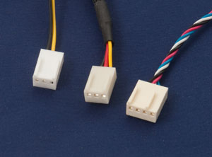
- 2-wire fans: These generally use a 3 pin header connector with pin 1 as ground, pin 2 as +12V and pin 3 vacant.
- 3-wire fans: These are the same as 2-wire fans with the addition of a tachometer output on pin 3. The tachometer can generate 1, 2 or 4 pulses per revolution and the fan controller will accommodate all of these.
- 4-wire fans: This is an Intel specification and is the same as a 3-wire fan with the addition of a PWM speed control input on pin 4. The connector is a special type that allows 3 pin and 4 pin connectors to be interchanged.
The photo on the right shows what these connectors look like.
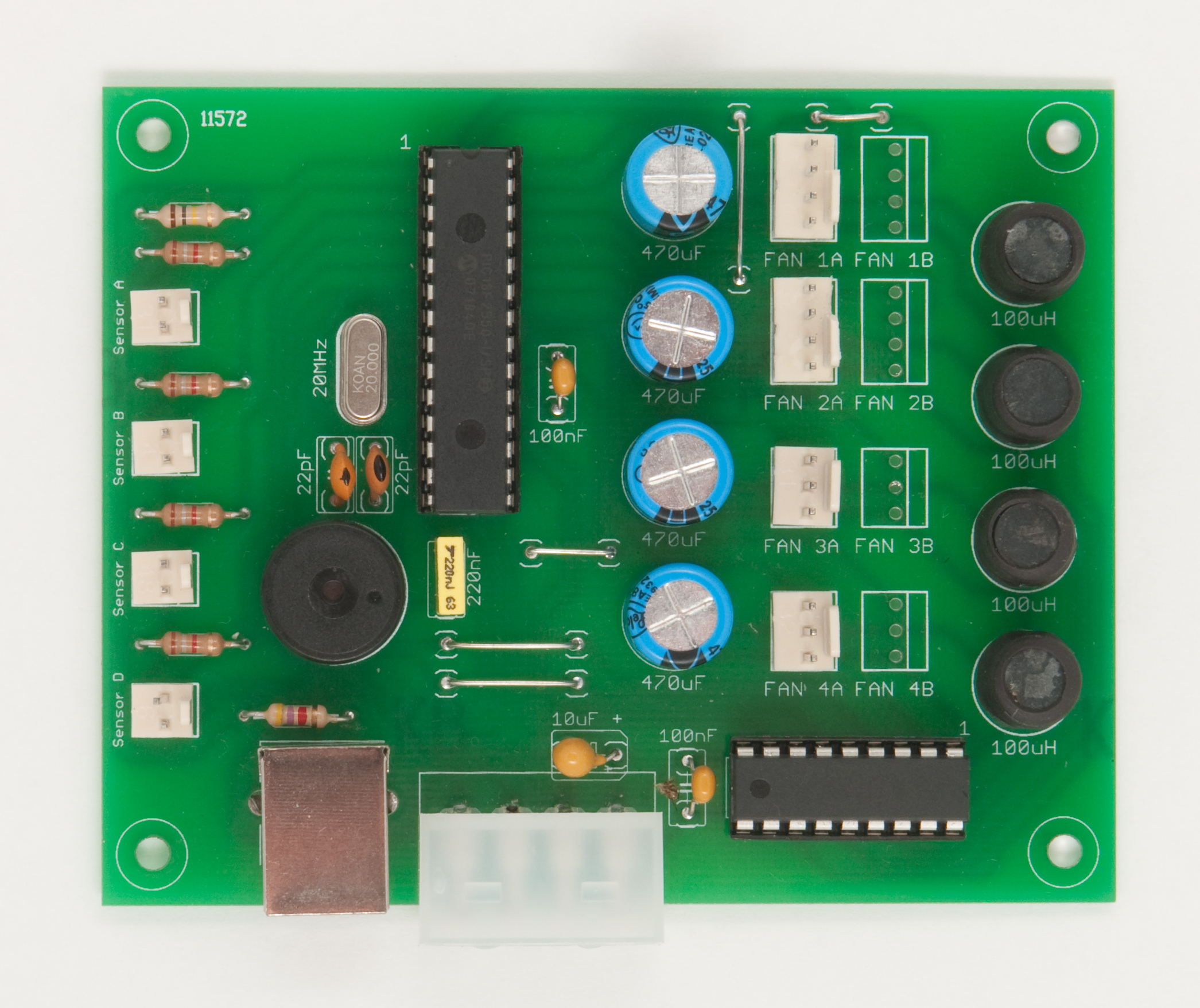
The Circuit
The circuit below shows just how simple the fan controller is. In the centre is a Microchip PIC18F2550 microcontroller, it reads the voltage from the temperature sensors (on the left) and controls the voltage converters on the right. It is by varying the voltage output of the converters that the microcontroller can control the speed of the fans.
Each voltage converter is implemented as a buck converter. The microcontroller generates a string of pulses on each output for each buck converter and, by varying the pulse width, the microcontroller can vary the output voltage. In this implementation the pulse rate is 2.5KHz and the pulse width varies between zero and 170µS to give an output between zero and 12V. Note that IC2 does double duty as a fast switch and a diode - both required in the buck converter design. For $2.20 this is a handy little chip.
As you can see, there are four buck converters and on each output we can have a pair of fans for a total of eight fans. Each buck converter is controlled independently with different control characteristics and can drive a load of up to 250mA. As a normal computer case fan draws less than 120mA this allows you to connect two fans (as a pair) onto each output. You should check each of your fans and if they draw more that 125mA (and less than 250mA) then that fan must be the only one connected to that particular buck converter output.
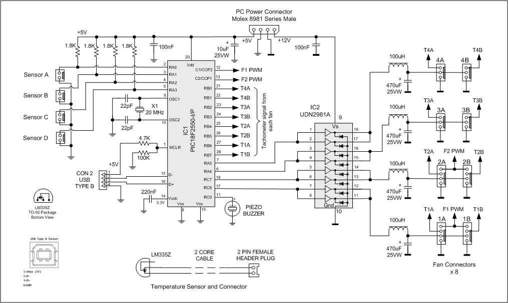
Click on the diagram for a large image
This is a simple buck converter design and the output contains a lot of switching noise and is not very linear with respect to the control signal. This does not matter as a fan is just an electric motor and does not need precise control to vary its cooling power (and noise). What is important is that we control the fan's speed by varying its supply voltage. Another method of control, often used in simple designs, is to rapidly switch the fan's supply voltage off and on but that has the unwanted side effect of scrambling the tachometer output, preventing us from measuring the fan's speed.
When a fan is configured as a 4-wire fan the controller will hold the output of the voltage converter at 12V and control the speed of the fan by generating a PWM signal. This signal is made available by the microcontroller on pins 12 and 13 and is used to control up to four 4-wire fans on connectors 1A, 1B, 2A and 2B. The design of the connectors and the circuit also allows you to plug 2-wire or 3-wire fans into these connectors and they will operate as normal (ie, voltage controlled).
The tachometer outputs from the fans are wired directly back to the microcontroller which measures and reports the speeds in RPM. The tachometer outputs are open collector so we enable internal pullup resistors within the microcontroller.
The other components surrounding the microcontroller are standard. The buzzer is used to make an audible alarm when a fan or sensor has failed. The crystal (X1) provides the 20MHz clock and the USB connector is wired directly to the USB transceiver within the micro. The 5V provided by the computer when the USB cable is plugged in is connected to pin 1 of the micro and is used to tell the firmware when to start communicating over the USB.
The Software
The great feature of this design is that it comes complete with desktop software for setting up the controller and monitoring its operation. It will work on the modern versions of Windows in both 32 and 64 bit modes although some users have reported difficulties with Windows 10. An alternative version developed by Pavel Spiridonov is also available - it runs on both Windows 10 and Linux (details are near the top of this page).
Unfortunately Mac users are left out but there is some good news. The Fan Controller implements the CDC (Communication Device Class) protocol over USB and there is native support for this in Apple OS/X. The Fan Controller appears as a standard serial communications device to the operating system and the commands accepted by it are simple ASCII strings, so it would be easy to write your own software or use simple scripting to communicate with the controller.
These images show my version:
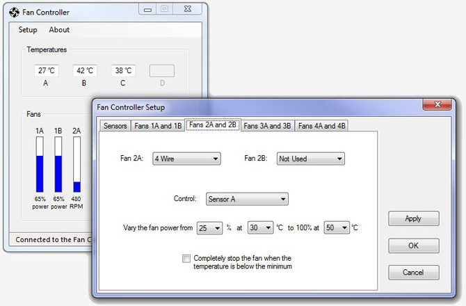 The software works in two modes. In the monitoring mode it will display the temperatures (in °C or °F) and the speed of the fans in RPM. If the fan does not have a tachometer it will display the output power of the voltage converter (0 to 100%).
The second mode is used to configure the controller. Once you have configured the controller you can uninstall the software as the settings are saved within the microcontroller. Or, you can leave the software installed to monitor the operation of the controller.
When configuring the controller you can select:
- What sensors are connected and how the temperature should be displayed (in °C or °F).
- The type of each fan connected (2, 3, 4 wire or not connected).
- The sensor used to control each pair of fans. This can be sensor A, B, C or D. It can also be the difference between D and sensors A, B or C. Finally you can set the control to manual for a fixed speed or testing.
- The control characteristics. As you can see in the above screenshot, the power (voltage supply) for each pair of fans can be varied from some minimum setting to 100% over a range of temperatures.
The software is available in the download section below and comes in three parts:
- The software package for your computer. This includes the serial over USB device driver for Windows and the desktop software shown above. You must be connected to the Internet when you install the desktop application as it uses the Microsoft .NET runtime and during installation components of this will be downloaded from the Microsoft web site.
- The program for the microcontroller. This is in the form of a HEX file and must be loaded into the microcontroller using a PIC programmer (not required for the Altronics kit which comes with a pre programmed microcontroller chip).
- The source code package which includes the source code for both the firmware and the desktop application. Both use free development environments (Microsoft’s VB Express 2008 and Microchip’s MPLAB C18 compiler). So you can experiment and modify both the firmware and desktop software to suit your own needs - or just look through it to satisfy your curiosity as to how it was done.
The software will install and run on a computer even though you have not built the fan controller. It was written in this way so that you can test the software and see if it and its characteristics will suit your requirements. It is free and you can easily uninstall it - so why not download it and give it a go?
This section is for readers who know how to source the parts and want to make their own fan controller from scratch. The alternative is to buy the Altronics kit which includes all the parts and a pre programmed microcontroller chip. The kit also includes the magazine article which goes into more detail than I have space for here.
The PCB design, the parts list, circuit and all software are available in the Construction Pack which can be downloaded from the bottom of this page.
The PCB is single sided and uses wide tracks with no tracks going between IC pins (these are Silicon Chip design guidelines) so you can easily make it yourself. If you do not want to make your own PCB you can send the Gerbers included in the Construction Pack to almost any PCB house for fabrication (see this page for some examples).
The parts list includes pointers to suitable suppliers. For the semiconductors the best (and cheapest) source is www.futurlec.com. If you do not have a PIC programmer you can purchase the PIC18F2550 pre programmed with the firmware from Silicon Chip magazine (link).
 The 4 pin connectors used for fans 1A, 1B, 2A and 2B must be specially fabricated The Intel specification includes a drawing of this connector and the best way to make one is to take a standard 4 pin header PCB connector and trim the plastic tongue so that a 3 pin connector can be plugged onto pins 1, 2 and 3 (leaving pin 4 unconnected). If you click on the photo above you can download a high resolution image that will illustrate this simple surgery.
When purchasing the inductors you must make sure that you use HF chokes with a current rating above 1 amp. Tiny RF inductors are not suitable, even if they have the correct inductance, as their resistance will be too high.
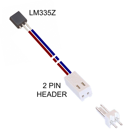
The sensors consist of an LM335Z temperature sensor wired to a 2 pin header plug which is plugged into the fan controller board.. The diagram on the left will help you in assembling the cable. Note that the left hand pin on the LM335Z is used for temperature compensation and can be cut off as we do not use that feature.
Installation
The PCB is designed to fit into a 3½ inch disk drive bay but you can place it anywhere inside your computer. Depending on the location selected you may need to make up mounting brackets to hold it in place.
The controller is designed primarily to control case fans but it can also control the fan on the CPU or graphics card. In this case you must use a dedicated sensor clamped to the heatsink and thermal conductive paste so that the fan controller can detect and respond to a rapid increase in temperature.
You can also use the controller to manage the fan inside a power supply - but these are dangerous devices with many of the components inside running at the full 230V mains potential. You should not open one up unless you know what you are doing and in that case you will not need any advice on what to do.
The firmware running in the microcontroller is designed to be stable but there may be a case where it has been set to an “impossible” configuration. To correct this you can reset the micro to its initial default condition by temporarily placing a wire link that shorts the connector pins for Sensor A together while you apply power to the circuit.
| Firmware HEX file for the PIC2550 microcontroller. Version 1.0 | DOWNLOAD |
| Windows software package (device driver and application). Version 1.1 | DOWNLOAD |
| Source code for both the microcontroller (v1.0) and the Windows application (v1.1) | DOWNLOAD |
| Construction Pack (includes parts list, schematic, PC board, etc) | DOWNLOAD |
So, have fun with the Intelligent Fan Controller.
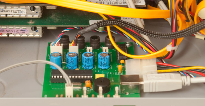
The photo below shows one of them mounted in the bottom of my multimedia computer.