
Precision Analog Clock
![]()
![]()
![]() Are you tired of having a wall clock that is always a little too fast or too slow? Is adjusting the hands for daylight saving a chore that you would rather not do?
Are you tired of having a wall clock that is always a little too fast or too slow? Is adjusting the hands for daylight saving a chore that you would rather not do?
How about a clock that is always accurate - to the second?
This project will convert an ordinary wall clock into a precision timepiece that will stay accurate to within a few seconds and has a battery life of up to eight years using two C size cells.
Even better, you will not have to adjust it for daylight saving - this clock driver will automatically do it for you by advancing the hands by one hour at the start of daylight saving and retarding the hands by the same amount at the end of daylight saving.
This is a clock that you never have to touch and will always tell you the correct time.
How is this precision achieved? It is done using a low cost GPS or WiFi module to get the accurate time and a microcontroller with some clever firmware to control the clock's hands.
 The Clock Driver will cost about US $30 in parts to build and the whole thing can be put together in a few hours. The full construction details are provided below and the firmware is completely free to download and use.
Almost any analog wall clock can be used. All that you need do is modify the movement to disconnect the internal controller and bring out the connection to the clock's motor. The new controller described on this web page will take over the job of controlling the hands and will keep them accurate to within seconds.
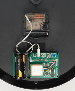
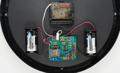
The image on the right shows the controller board with two AA batteries mounted on the back of a modified Ikea TJALLA sweep clock.
This project was described in the September 2022 issue of Silicon Chip magazine. This web page provides a shorter description so, if you would like the full story, you are encouraged to read the magazine article. The November 2022 issue has an addendum describing how to use a WiFi module with the clock.
Back issues of the magazine can be purchased from Silicon Chip or electronic access can be purchased for about the cost of the printed issue - so it is good value.
Clock Types
There are two types of wall clocks that are generally available for the home. Stepping clocks where the second hand moves once a second (often with a loud "tock" sound) and sweep clocks where the second hand moves continuously and silently around the dial.
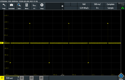
Stepping clocks are the most simple and the motor in them must be driven with alternating positive and negative pulses delivered once a second and with a pulse width of 30 to 45 ms. With each pulse the clock will advance by one second. The top oscilliscope capture below shows this waveform.
 |
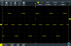 |
Sweep clocks use a continuous stream of alternating positive and negative pulses with each pulse 31.25 ms in width and an idle time of 31.25 ms between each pulse. This means that there will be 16 pulses in each second and the frequency of the drive is 8 Hz. This waveform is also shown on the right.
Some sweep clocks (notably from Ikea) require a wider pulse and this can be specified when configuring the firmware (see below).
Within the sweep clock's motor the momentum of the spinning rotor will keep it moving between each pulse so the second hand will move continuously (ie, sweeps) around the dial.
In both cases the pulses need to be between 1 V and 1.6 V (ie, the output of a standard carbon or alkaline cell). The clock driver will increase the pulse width at low battery voltages so sweep clocks should continue to operate with a battery voltage of 0.95 V or even less while stepping clocks will typically stop with a drive voltage of 1.0 V or less.
Stepping clocks are more common and can be found in most general stores while sweep clocks are often harder to find and more expensive. The firmware used by the Clock Driver can be configured for either type (see below) so you can use whatever type of clock you fancy.
The battery life for either type is similar and the only real difference is that stepping clocks are generally more robust and make a loud "tock" sound every second while sweep clocks are more fragile but silent.
How It Works
The Clock Driver is based on the Microchip PIC16LF1455, a low cost microcontroller which has a very low power consumption. Referring to the block diagram below, the microcontroller has a 32.768 KHz crystal oscillator which drives a 16-bit timer. Both of these will continue to run when the CPU is put to sleep and have a current drain of just a few microamps.
When it is time to generate a pulse for the clock's motor the timer will wake up the CPU which will drive its output high or low to initiate the pulse. Following this it will reset the timer for the required pulse width and go back to sleep again. When the timer re-awakens the CPU, the CPU will terminate the pulse by setting its output to high impedance, reset the timer for the start of the next pulse and go back to sleep again.
This continues forever with the CPU jumping in and out of sleep while toggling its output pin. Most of the time the microcontroller is sleeping and, as a result, its average current consumption is quite low at about 18 µA.
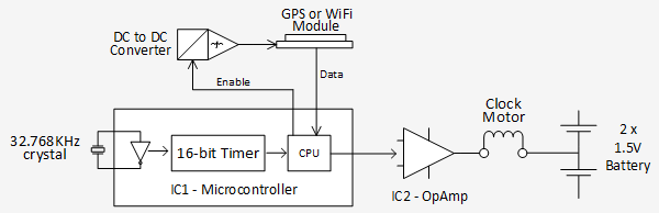
IC2 is an operational amplifier and its job is to buffer the signal and drive the clock's motor. When its output is driven high the current for the clock's motor will be drawn from the top battery and conversely, for a negative pulse, the current will be drawn from the lower battery. At idle between pulses its output will be at the midpoint of the two batteries so no current will be drawn. As a result, the power needed to drive the clock's motor will be divided evenly between the two batteries. Typically a clock's motor will draw 140 to 170 µA (average) which, by using this arrangement, is 70 to 85 µA from each battery.
Time Synchronisation
From time to time the microcontroller will synchronise the position of the clock's hands with the time from the network of GPS satellites or by using your WiFi network to access a time server (both of which are VERY accurate). Initially the interval between synchronisations is set at 12 hours but over time this will be progressively increased up to 5 days.
If it is time to synchronise, the CPU will not go to sleep but will drive the enable pin of the DC to DC converter to start it operating. This is a Microchip MCP16251 which is configured to generate an output of 4 V and this is used to power either a GPS or WiFi module. After a short time (typically less than a minute) the microcontroller will get an accurate time and it will then turn off the DC to DC converter to conserve the battery.
While waiting for the time the DC to DC converter and the GPS or WiFi module can draw quite a lot of current (as much as 100 mA) but, as this occurs infrequently, the drain on the batteries averaged over a long time is quite low at about 5 µA.
The firmware keeps track of the exact position of the clock's hands and with the correct time the firmware can then adjust for any error in their position by driving the clock's motor faster or slower to make them agree with the time from the GPS or WiFi module. For a stepping clock this is done by stepping twice in a second or skipping a step entirely. For a sweep clock the pulse train will run fast or slow by 12.5% for eight seconds thereby advancing or retarding the clock's hands by one second in that time.
Based on the error discovered at synchronisation the firmware will then calculate what corrections will be needed to keep the hands accurate during the next period up to the next synchronisation. This correction is done by occasionally running fast or slow by one second to compensate for this error. As a result, the clock will stay reasonably accurate during the entire period between GPS or WiFi synchronisations.
This correction mechanism will start operating after the first day or two after the clock has started running and will continue for the life of the batteries. Therefore, over the long term, the clock will always be accurate, regardless of any error in the 32.768 KHz crystal's frequency or other factors such as ageing of the crystal.
Time Source
The firmware will work with either a GPS module or a WiFi module and both have similar performance and keep the time equally well.
The specified GPS module is a V.KEL VK2828U7G5LF which is a good performer and relatively cheap (approx US$10 on Banggood.com and eBay). As part of how GPS works the satellites transmit an accurate time signal and this is used to synchronise the clock. A GPS module has the advantage of not requiring a WiFi connection to access the Internet but it can sometimes struggle to get a signal, especially in a multi level house with a steel roof.
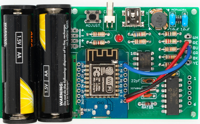 |
| The Clock Driver board using a WiFi module. On the top right is the DC to DC converter and below it the 14-pin chip is the PIC16LF1455 microcontroller |
The specified WiFi module is a Lolin or WeMos D1 Mini. These are readily available (eg, Jaycar part XC3802) and if you search on eBay you will find hundreds of sellers offering them for US$10 or less.
Using this as the time source has the advantage of not being affected by signal variations but it does require more work to load its firmware and it needs a WiFi network which is connected to the Internet. The module will use this to get the time from a public time server which accurate within a tenth of a second.
If you have a strong WiFi signal and a reliable connection to the Internet a WiFi module would be the best choice for the time source. However, the firmware running on the microcontroller does not care which module is being used and in most cases either will work fine.
Daylight Saving
When configuring the clock driver (described below) you can specify if daylight saving compensation should be applied and the rules for your particular location. The firmware is flexible enough to cope with the daylight saving requirements for most countries around the world, although there are some that are just too complicated (for example Iran).
At 2:00 AM on the day specified for the start of daylight saving the clock will run fast to add the required hour. For a stepping clock it will step twice a second for an hour but for a sweep clock this will take eight hours because it cannot run as fast as a stepping clock. At 3:00 AM on the day specified for the end of daylight saving a stepping clock will subtract an hour by stopping its hands for exactly one hour while a sweep clock will subtract an hour by running slow for eight hours.
In the United Kingdom (time zone zero) the daylight saving start and end times are one hour earlier.
Following the adjustment for daylight saving the clock will resume its normal activity, keeping the time accurate to within a few seconds.
Configuring the Clock Driver
The Clock Driver defaults to a stepping clock with no daylight saving. So, if that is all that you need, you do not have to configure anything.
However, most people will need to configure the Clock Driver and you do this by using the mini USB socket mounted on the driver board. When the batteries are inserted and the USB is plugged into a PC or laptop the LED on the PCB will flash three times to indicate that the firmware is in configuration mode and the Clock Driver will connect to your PC as a virtual serial port over USB.
When doing this it will imitate the Microchip MCP2200 USB/serial converter. Windows 10 and 11 are delivered with the correct driver installed but with other operating systems you may need to load a driver, and this can be found on the Microchip website at http://www.microchip.com/wwwproducts/en/MCP2200.
You also need to install a terminal emulator such as Tera Term (http://tera-term.en.lo4d.com) or Putty. This will display any text sent by the Clock Driver and send any keystrokes that you make back over the serial USB interface. You need to configure the terminal emulator with the number of the virtual serial port created by your operating system but other than that everying (including the baud rate) can be left as the default.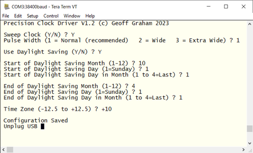
When you hit the Enter key you should see the header as shown on the right. Incidently, this image shows the configuration required for the east coast of Australia.
The first question is "Sweep Clock (Y/N) ?" and if you reply N followed by the Enter key you will configure the driver for a stepping clock. On the other hand Y will configure it for a sweep movement.
If you selected a Sweep Clock you will then be asked for the Pulse Width as a number from 1 to 3 (as illustrated above). For most sweep clocks this can be 1 for "normal". However there are a few clocks that require a wider pulse and the firmware can generate this if needed. The README file in the firmware download goes into this in more detail. You can read this file here.
The next question is "Use Daylight Saving (Y/N)?". If you reply N you are finished and you will be prompted to unplug the USB cable. On the other hand, if you reply Y you will then need to enter three bits of information for both the start and end of daylight saving.
These are:
- The month that daylight saving starts/ends with January = 1, February = 2, etc.
- The day of the week that daylight saving starts/ends with Sunday = 1, Monday = 2, etc.
- The position of that day in the month with the first of that day in the month being 1, the second 2, etc. 4 indicates that the day should be the last one in the month.
Finally, you need to enter the time zone in the format +nn.n or -nn.n. For example, Los Angeles is -7.0.
With this done you will be prompted to unplug the USB and when this is done the clock will restart, as if the batteries had just been inserted and it will run through its startup process (see below). This configuration only needs to be done once and it will be remembered, even when you change the batteries.
Starting the Clock
Before you start the clock you need to set the hands to exactly the next hour or half hour (whichever will come first). Then insert the batteries or unplug the USB.
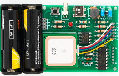 |
| The Clock Driver board using a GPS module. On the top edge is the tactile switch, the connector for the clock's motor, the LED and the USB socket . |
The firmware will then go into its startup routine. This consists of:
- The LED on the PCB will flash twice to indicate that it is in running mode.
- It will power up the GPS or WiFi module to get the correct time.
- While it is waiting for the module to return an accurate time the LED will briefly flash once a second.
- When the correct time is found the LED will change to a long flash every second and the module will be powered down.
- Precisely when the next half or full hour arrives the clock will start running and the LED will turn off.
When you set the hands of the clock the second hand will probably not be in the correct position. If you hold down the tactile switch on the PCB while the clock is waiting to start the firmware will drive the second hand around the dial and you can release the button when it reaches the 12 o'clock position.
That way the clock will start running with the second hand in the correct position.
Errors In Getting the Time
The firmware will treat both the GPS module and WiFi module the same when it comes to a failure in getting an accurate time. This could be caused by an insufficient GPS signal or, in the case of the WiFi module, an inability to reach the Internet.
On power up the firmware will wait forever to get the time and the clock will not start running until this has been accomplished. After the clock has started running the firmware will act differently; it will keep trying for 30 minutes and then, if it still cannot get the time, it will give up and retry every 24 hours until an accurate time is retreived. During this period the clock will continue to operate normally but the LED on the controller board will flash once a second as a warning that the time could not accessed.
 |
| The recommended GPS module (a V.KEL VK2828U7G5LF). |
GPS Module
If the GPS module is brand new, it can take up to 45 minutes to get its first lock on the satellite network. In this case you should place the clock face down outside with the GPS module pointing to the sky and leave it there for a while. The GPS module will store important satellite information in its internal flash memory so, following this initial startup, subsequent synchronisation's should take less than a minute or two.
WiFi Module
The WiFi module has a blue LED on the top which will illuminate while connecting to a time server. When connected it will change to a short flash every second. Generally the module will get the correct time in just a few seconds however, if it cannot access the Internet, the LED will remain illuminated and the clock will act as described above (ie, wait forever or give up and retry 24 hours later).
With either time source, when the GPS signal or WiFi/Internet is restored, the firmware will get the correct time and will immediately adjust the position of the clock's hands to reflect the correct time.
Accuracy
Most people are happy with a wall clock that is accurate to the minute and if that is you, then you do not need to be concerned with the following, which covers the factors involved in achieving extreme accuracy (to the second).
Sometimes, when the clock starts running, the seconds hand may start moving a second or two early or late. If you are particularly concerned you can check for this by using the National Institute of Standards web site (www.time.gov) to get the precise time and correct for even this slight startup error.
To do this hold down the tactile switch (while the clock is running) until the LED illuminates, then if you:
- Release the button immediately the firmware will advance the clock's hands by an extra second.
- Keep holding down the button until the LED extinguishes the firmware will retard the hands by one second.
Note that this should only be used immediately after startup to correct for any startup error. It is not needed while the clock is running normally and if it was used later it would interfere with the automatic correction mechanism built into the firmware.
The GPS or WiFi modules will report the time precisely on the second and the microcontroller has control over the position of the clock's hands with a resolution of one second. So, with everything else being equal and any startup error corrected (as described above) the clock's hands will be accurate to within ±1 second.
The main source of inaccuracy is caused by variations in the temperature, even by a few degrees. Over time the firmware will discover this error and correct for it but this can take as much as 5 to 10 days and during that period the clock can be slightly inaccurate. Typically this will be one or two seconds but, for example, a 15°C change caused by moving the clock from a warm indoors to a cold outdoors can cause a short term inaccuracy of up to 10 seconds.
To reduce this effect you should position the clock in a temperature stable location (eg, away from windows, air conditioners and heat sources) and do not move it around. But, even then, it is difficult to achieve a completely stable temperature so a temporary error of one or two seconds can be expected.
Many clocks, especially clocks with sweep movements, are susceptible to strong physical movement. This is because any acceleration caused by moving the clock will drag on the second hand causing the clock's motor to stall for a second or two. This error is not detected or corrected by the firmware so be gentle when moving the clock and, if possible, just leave it up on the wall.
As stated above, these factors are only significant if you are trying to achieve the perfect ±1 second accuracy.
Battery Life
In the design of the clock controller particular attention was given to minimising the power consumption and thereby lengthening the life of the batteries.
The clock's motor, the microcontroller and other circuitry will draw a total of about 90 to 110 µA from each battery averaged over the long term. Typical high quality AA batteries have a capacity of more than 2000 mA/h (terminating at 1 V) so, using these, the clock should run for about two years. High quality C cells have a capacity of about 8000 mA/h meaning that up to eight years is possible with these. However, in this case the batteries' internal leakage over this long time might reduce their lifetime.
You can also use AA sized Lithium Primary cells (ie, Energiser Lithium/Iron Disulfide) which have a capacity of about 3400 mA/h (with a light load and terminating at 1.2 V). These have a very long shelf life (20 years) so most of their capacity would be used to drive the clock and you could expect a battery life of about 3½ years.
If your clock stops running early it would be worthwhile measuring the voltage of the batteries when you remove them. Most clock movements will keep running down to 1 V or below and that is the sort of voltage that you should find. However, if your clock stopped running with a battery voltage significantly higher than this (say 1.1 V or 1.2 V), then that indicates that the clock movement is faulty and should be replaced. For a sweep clock it might also indicate that the Pulse Width in the configuration setup might need to be increased (see this note).
Note that this does not apply if you are using Lithium Primary cells as their output voltage will revert to about 1.2 V when removed from the clock, even though they are fully discharged.
Construction
 The Clock Driver is built on a PCB measuring 99 mm x 5 7mm. This includes the battery holders for two AA batteries.
If you wish you can cut off the portion of the PCB with the battery holders and mount the batteries separately. This particularly applies if you are using C cells or if you do not have enough space for the full size PCB.
The photo on the right shows such an installation using C sized batteries in separate battery holders.
Rather than list the boring detailed construction data (parts list, assembly notes, schematic, etc) on this web page I have bundled all of this into the "Construction Pack" which you can download from below. This includes everything that you need to know to build the Clock Driver including how to modify your clock and much more.
Finding the required parts can be tedious so if you do not want to do that you can buy a complete kit of parts including the PCB and GPS or WiFi module from Silicon Chip magazine (kit SC6472 costing A$55 + postage). This includes the microcontroller pre programmed with the firmware, so all you need do is solder it in and you are ready to go. For the full details follow this link or see the September 2022 issue of Silicon Chip.
Firmware Update
A new version (V1.2) is available for download below. It includes the ability to select wide and extra wide pulse widths for driving sweep clocks. You will only need to upgrade if you have a sweep clock that stalls or stops early before the battery is fully exhausted. The only known clocks that need this feature are Ikea clocks but there might be others out there. A ReadMe file in the firmware download describs this issue in detail.
Other than this there is no change, especially for stepping clocks.
To update the firmware you will need a PIC programmer. See this web page for more information.
NOTE: After the upgrade the firmware will need to be reconfigured.
| Construction Pack (parts list, schematic, PCB manufacturing files, etc) | DOWNLOAD |
| GPS Clock Driver Firmware V1.2 |
DOWNLOAD |
| Firmware Source Code V1.2 (Note: Requires Microchip XC8 Pro compiler V1.44) | DOWNLOAD |