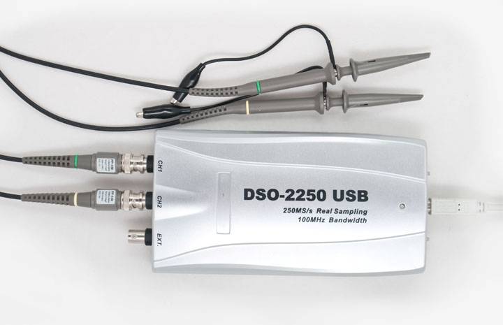
Hantek DSO-2250 USB Oscilloscope
![]()
![]()
The Hantek DSO-2250 is a 100MHz oscilloscope that plugs into your computer via USB. It uses software on the computer to control the device and display the results. It will sample its input at 250MS/s and has a buffer depth of 512K samples.
It sounds good, and it is a good device. When I purchased it in mid 2008 it cost US$329, which was very cheap for something with this capability. But in the end I replaced it with a more conventional stand alone oscilloscope.
One of the problems that I had at the time I was purchasing was that there were few reviews of it, so this article is intended to help correct that. It also questions whether a USB oscilloscope is really the way to go.
The DSO-2250 is sold by a number of companies, often under their own, in house brand name, but they all keep the model number (DSO-2250). In Australia Jaycar sell its slower speed cousin (the 40MHz DSO-2090).
What Does It Do?
The specifications for the DSO-2250 are available from here I won’t repeat all the specs but the high points are:
- Two channels plus an external trigger input.
- 100MHz bandwidth with sensitivity from 10mV/division up to 10V/div.
- 250 MS/s sample rate and 512K sample memory (not at the same time).
- Wide range of measurements including Vpp, overshoot, rise/fall times, period, frequency, pulse width, spectrum analyser, etc.
Essentially the oscilloscope does everything stated in the brochure and user manual. I have not tested all the specs but it seems to meet the important ones like bandwidth, sample speed, etc. You can read the manual to get a detailed idea of what it does and how it works. Also, for what it is worth, you can find the manufacturers website here.
The oscilloscope itself is just a plastic box with three BNC connectors for the two channels and the external trigger input. On the other end is the USB socket. Once you have plugged the USB into your computer, installed the driver and software you have a full featured oscilloscope running on your computer screen. One of the great benefits of this is that you can make the window as large as you want so you get a wonderful large screen oscilloscope, great for observing the details of a waveform.
The screenshot below is of the newer software (ver 7) and gives you a good idea of what you will see.
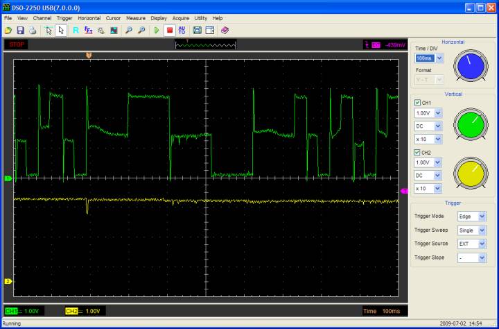 This is a stored snapshot of the waveform and in the top left of the screen you can see “STOP” which means the oscilloscope has triggered and stopped. In the top centre you can see a graphic which shows the displayed section of the waveform in relation to the whole waveform stored in memory. The orange marker represents the trigger point. On the right (in purple) you can see that the trigger was set for a falling edge on the external trigger input and the trigger level was –439mV.
On the main screen you can see the orange marker (at the top) indicating the trigger point. On the left hand side the green and yellow markers represent the zero voltage points for channel 1 and 2. On the right hand side you can see a purple marker representing the trigger point for the external trigger. All these markers can be clicked on with the mouse and dragged to new positions. This make it very intuitive and easy to adjust zero and trigger points.
At the bottom of the screen you can see the sensitivity of channels 1 and 2 (1V/div) and the timebase (100mS/div). On the right hand side is the “control panel”. You can adjust the graphic knobs by clicking on the outside edge with the mouse and making a circular motion with the mouse. I found it easier to click on the dropdown boxes and select the value that I needed.
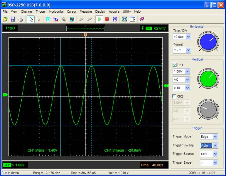 The above screenshot shows some of the on screen measurements that are possible. The green lettering near the bottom of the screen show that channel 1 has an amplitude of 1.4V RMS and a mean (zero point) of –20.9mV. The blue lines on the screen are cursors which can be dragged into position—at the very bottom their values are displayed, in this case the frequency is about 12.5KHz , the period is 80uS and the peak to peak voltage is 4V.
This screen shot is from the software running in demo mode (not connected to the oscilloscope). You can get a good idea of the capabilities of the software by downloading it yourself and running it in demo mode.
All the screen shots are captured by the software itself. All you need do is select File->Image and you can save a full sized and impressive image. This is invaluable as it allows you to examine the images later and compare them with waveforms recorded under different circumstances.
Positives and Negatives
The good features of the oscilloscope are that it does what it says that it does and it is very good value for money. The negative points might sound trivial but they eventually forced me to go out and buy another oscilloscope with a more conventional design (ie, stand alone with knobs and its own screen).
Firstly, the usability of the software is poor. The current version on the manufacturers website (ver 6) is extremely clunky and difficult to use. Eventually I found a more updated version (ver 7), that is used in these screen shots and, while it is much improved, it is still difficult to use. The graphic “knobs” are a pain to use so I ended up using the drop down lists instead, but that is still slow and messy compared to just twisting a knob on a conventional oscilloscope. Also, many features are hidden deep within the menu structure (see the screenshot below for an example) and other features such as zooming the horizontal scale on a captured trace are so convoluted that you tend to skip them.
 A minor annoyance is that my DSO-2250 has a permanent offset on channel 1 between the zero reported by the software and zero measured at the probe tip. You can see that offset on the screenshot to the right—the zero marker for channel 1 (the green icon on the left) is set exactly on the centre line, but the signal trace is half a division offset from that (the probe tip was grounded).
The oscilloscope also suffers from permanent ADC noise on the inputs, regardless of the sensitivity or other settings. You can see this noise on the green trace in the screenshot to the right. I admit that this is an unfair complaint as most digital oscilloscopes have this noise but their small screens generally do not show it.
I also found that with a USB oscilloscope you cannot just flick a switch to fire it up. You need to start the software, wait for it to load, make space on your screen, etc. Fortunately I always have a computer running on my workbench but many people do not and that would be an even greater impediment.
The upshot of all this was that while I used the DSO-2250 for special stuff I kept my 25 year old oscilloscope (a 20MHz CRO) on the bench and this is what I reached for when I wanted to make a quick measurement. And when I did that I found myself wishing for some of the neat features of a modern oscilloscope. In the end I bought myself a proper digital oscilloscope—with knobs that I could twist, startup in a few seconds and a built in display (the Rigol DS1000 Series Oscilloscope).
Support
Support is another negative for this device. When I first got this oscilloscope I kept checking their English website for updated software but nothing new was ever posted. Eventually I contacted Hantek support via email and got a prompt reply with a “secret” link to the latest version. When I last checked they had finally posted the update to their main website (here), nine months after it was first available.
Their support site is in Chinese but another support site (here) has limited support for English speakers. I know that we cannot expect everyone in the world to speak English but if they want to be successful in English speaking markets they should provide better support in that language.
 On Sample Speed and Memory Depth
One issue that seems to be common amongst digital oscilloscope manufacturers is that they quote a sample speed and memory depth in their specifications but you cannot get both at the same time. What I would really like is to be able, without any caveats, to freeze a wave form and, if I wanted to, zoom in on a section by expanding the horizontal scaling by (say) 100 times. After all, this is what a digital oscilloscope with a large memory depth should be about. But, in practice, digital oscilloscopes like to capture to a small and fast memory and you must specially select their extended memory depth and then it will only work at a slow sampling rate.
The DSO-2250 also practices this deception. Its standard memory is just 10K samples and if you configure it to its full memory size (512K) you are limited to a sweep of 200uS/div - if you try to go faster you are warned off with an intrusive dialog box . As a result you tend to leave it running with a mere 10K memory depth, which is dumb when you purchased an oscilloscope with much more than that.