
Micromite LCD Backpack
![]()
![]()
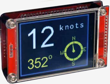 The Micromite LCD Backpack is a low cost microcontroller running a powerful BASIC interpreter with a touch sensitive TFT LCD display.
It has been immensley successful with thousands built by enthusisasts around the world and used for everything from navigating a boat to controlling a heating system.
The Micromite LCD Backpack is a low cost microcontroller running a powerful BASIC interpreter with a touch sensitive TFT LCD display.
It has been immensley successful with thousands built by enthusisasts around the world and used for everything from navigating a boat to controlling a heating system.
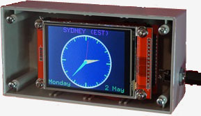
The colourful LCD panel can display text and graphics in 65,536 colours on its crisp 320 by 240 pixel display. You can draw buttons and other controls on the display and the user can select these using the touch sensitive feature of the LCD panel .
The Micromite can interface to many devices including switches, relays, LEDs, IR remote controls and more. Using the serial, I2C or SPI protocols you can also get data from a host of sensors.
The Micromite LCD Backpack uses about a dozen parts and can be built in half an hour.

The backpack itself is a PCB which mounts on the back of a common LCD display making a two layer "sandwich". The complete assembly is designed to plug into a solderless breadboard where any interface components can be tested. Then, when the design is complete, the interface circuit can be transferred to a custom PCB or strip board which can be mounted on the back of the Micromite LCD Backpack making a three layer sandwich.
The main components
are the Micromite which costs about US$4, an 8-bit microcontroller (US$2) and a 2.8" LCD panel typically costing $7 on eBay. The result is a low cost but powerful controller which is very easy to program.
New Version
This page describes version 2 of the Micromite LCD Backpack. This includes a chip which acts as both a USB interface to the Micromite's console and a PIC32 programmer for updating the Micromite's firmware.
This feature costs only a few dollars to implement and is great value for what it does. In the original Backpack design both of these functions had to be supplied by external devices. The original version is still good for many tasks and it has its own web page
Version 2 of the Micromite LCD Backpack was described in the May 2017 issue of Silicon Chip magazine. This web page provides a short description but if you want the full story you are encouraged to read the magazine article. Back issues of the magazine can be purchased from Silicon Chip or electronic access can be purchased for about the cost of the printed issue, so it is good value.
Using the Backpack
These are just a few examples of what you can do with the device.
 |
 |
 |
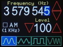
| A digital synthesised function generator (link). The touch screen allows you to adjust the waveform, frequency, signal level, etc. No physical controls are required and its operation is straight forward and intuitive. |
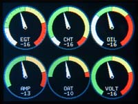
An engine monitor with six gages. All gauges are updated in real time and respond smoothly to their input. Program created by Peter Mather (matherp) on The Back Shed forum. |
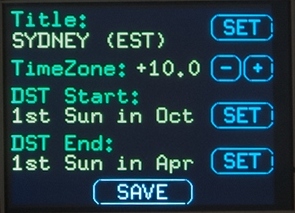
This example shows a typical configuration menu with touch sensitive buttons. Many manual switches and knobs required for a typical project can be replaced with graphical touch sensitive objects such as these. |
Basic Specifications are:
- Colour TFT LCD 320x240 pixels, 65536 colours. 2.8" diagonal measurement. Touch sensitive screen with the coordinates reported in pixels.
- Eleven input/output pins. All can operate as digital input/outputs and four can operate as analogue inputs. Three additional I/O pins for SPI use. Digital I/O sink or source capability for each pin is 15mA.
- MMBasic interpreter with 59KB program space and 53KB RAM (for variables and other uses). This will cater for programs up to 2500 lines.
- USB interface to the Micromite's console over which you can enter and edit your BASIC program.
- Graphic commands include CLS, PIXEL, LINE, BOX, RBOX, CIRCLE, TEXT and BITMAP using any of the 65536 colours.
- Two methods of controlling the LCD brightness - either under program control or via a trimpot.
- Communications protocols include I2C, asynchronous serial, RS232, IEEE 485, SPI and 1-Wire.
- Built in support for IR remote controls, temperature and humidity sensors, distance sensors, numeric keypads and battery backed clocks.
- Built in programmer which can be used to load the initial Micromite firmware and update it with new releases.
- Power supply 4.5V to 5.5V with a current drain of 100 to 225mA.

Other Useful WEB pages
Before you get too far into the Micromite LCD Backpack you should also explore the Micromite which is at the heart of this device:
Version 2 of the Micromite LCD Backpack includes a PIC16F1455 microcontroller (dubbed the "Microbridge") which provides a USB interface to the Micromite's console where you can enter and edit your BASIC program and a PIC32 programmer which can be used to load the initial Micromite firmware and update it with new releases. This web page does not go into the details of the Microbridge chip so you should read this web page for details of how to use it and how it works.
Circuit
The circuit is relatively simple (click on the image for a full resolution version):
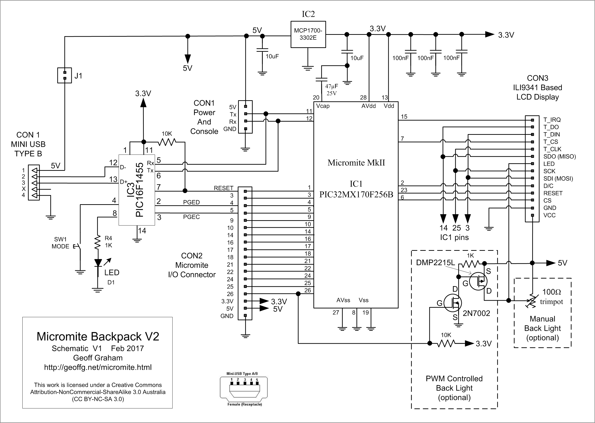
IC3 is a PIC16F1455 microcontroller programmed with the Microbridge firmware (see this page for the details). It provides a USB interface to a desktop or laptop computer which can then access the console interface on the Micromite for entering and editing the BASIC program running on the Micromite.
When running as a USB/serial converter pin 5 on the PIC16F1455 is the receive data (ie, data from the Micromite to USB) and pin 6 is the transmit data (data from the USB to the Micromite). These signals are also run to the edge pins for the console connection (CON1) in case you build this PCB but for some reason do not plug the Microbridge (the PIC16F1455) into its socket. In this case you can use an external USB/serial converter.
The PIC32 programming interface to the Micromite is via pins 7, 2 and 3 which provide the reset function, the data and the clock signals. These connect to pins 1, 4 and 5 respectively on the Micromite. The programming output on the PIC16F1455 is only active when it is in programming mode, so the PIC16F1455 does not interfere with the Micromite when it is using its pins 4 and 5 as general I/O pins.
As described on the Microbridge webpage, switch SW1 is used to select the PIC16F1455's programming mode and the LED D1 is used to indicate the mode (illuminated when in programming mode).
.jpg) The Micromite (IC1) directly drives the LCD display on CON3 using its SPI interface and a few additional control signals.
The Micromite (IC1) directly drives the LCD display on CON3 using its SPI interface and a few additional control signals.
CON2 is the main input/output connector with eleven general purpose I/O plus three additional pins reserved for SPI communications. This connector is designed so that it can be plugged into a solderless breadboard for program development.
The Backpack is powered by 5V with a maximum current draw of about 250mA (depending on the backlight brightness). This voltage can be supplied via the USB interface if jumper J1 is shorted otherwise it can be supplied via CON1 (which would be normal if the Backpack was being used as an embedded controller).
This 5V supply is used by the LCD display panel and dropped to 3.3V by IC2 for the Micromite. There is a third power supply of 1.8V inside the Micromite which is used to power the 32 bit CPU. The 47µF capacitor on pin 20 of the microcontroller is used to filter this power supply. The capacitor used here must be a tantalum or ceramic type. Do not us an electrolytic as that may prevent the CPU from starting.
Backlight Control
For controlling the brightness of the LCD's backlight you have two choices. The first is to populate Q1 and Q2 on the PCB and their associated resistors (this area is marked with a silk screened box on the PCB). When you do this PWM 2A on the Micromite can be used to control the brightness from within a program.
Alternatively you can populate the PCB with R1 which is a 100Ω trimpot that limits the current drawn by the backlight LEDs and therefore the brightness. The LCD panel has a 3.9Ω resistor in series with the backlight power input so you will not burn it out if at maximum brightness.
If you installed the components for the programmed controlled backlight the brightness is controlled via the PWM command in MMBasic and the associated pin (pin 26) is not available for general I/O.
By default the backlight will be at full brightness but it can be controlled with the following command:
PWM 2, 250, xx
where 'xx' is the percentage of full brightness required. This can range from 0 to 100.
As an example, you can fade from full brightness to black over half a second using the following :
FOR i = 100 to 0 STEP -1
PWM 2, 250, i
PAUSE 5
NEXT i
Sourcing The Parts
A full kit of parts including the LCD display panel is available
from Silicon Chip magazine. Buying this kit and a copy of the magazine article is the easiest way to build the Backpack.
If you want to source your own parts you should refer to the parts list included in the construction pack (which can be downloaded from the bottom of this page).
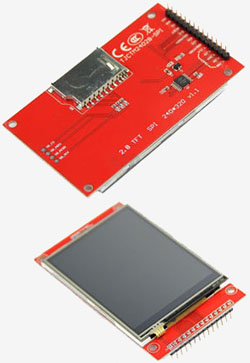
The LCD display panel can be easily found on eBay by searching for "ILI9341" which is the name of the controller used in the LCD panel. These come in a number of different sizes however the Backpack PCB is designed to match the mounting holes of the 2.8" version. The Micromite will also work with other sizes of the ILI9341 display but you will have to invent an alternate mounting arrangement
There are many versions of the ILI9341 display on offer but the panel that you purchase should look like the one illustrated on the right. This is important, do not purchase anything else as it may not work with the Micromite!
Refer to the Microbridge webpage for details of sourcing the PIC16F1455 microcontroller (IC3) and programming it with the Microbridge firmware.
The PIC32 microcontroller (IC1) can be found in many places. Microchip Direct sell the blank microcontroller for US$4.03 (for a single chip). Other suppliers such as Element 14, RS Components, etc also sell the blank chips at a slightly higher cost. Note that you do not need to purchase the PIC32 pre-programmed because using the Microbridge (the PIC16F1455) you can program the PIC32 yourself (check the Microbridge webpage for how to do this).
The Microchip MCP1700-3302E/TO voltage regulator can be found at Element14, Microchip Direct and others. There are also many other voltage regulators that can be used - the critical parameters are 3.3V output, low dropout and a current rating of at least 300mA.
The printed circuit board design is included in the construction pack and it can be made by many companies (usually based in China). I use ITead Studio Prototyping Service and Seeed and I am happy to recommend either of them but I have also heard good reports about Futurlec and Gold Phoenix.
.jpg)
Construction
The construction pack for the Micromite LCD Backpack can be downloaded from the bottom of this page. It contains everything you need to build the Backpack including the design for the printed circuit board, parts list, schematic and construction notes.
The completed PCB and the display should be joined together using spacers and screws as shown on the right and below.
Projects Based on the Backpack
 This website hosts five projects based on the Micromite LCD Backpack.
These are intended to demonstrate what can be done with this technology and provide a source of programming ideas and inspiration.
This website hosts five projects based on the Micromite LCD Backpack.
These are intended to demonstrate what can be done with this technology and provide a source of programming ideas and inspiration.
You can check them out by clicking on the links below:
- The Garage Parking Assistant.
- A Boat Computer.
- A Super Clock.
- DDS Function Generator.
- Air Quality Monitor.
Acknowledgments
The author would like to very much thank Peter Mather (matherp on The Back Shed forum) for demonstrating that the Micromite can drive a variety of LCD display panels and then developing the ILI9341 driver.
Also, a big thank you to the many people on The Back Shed forum who, over a period of six months, acted as beta testers to ensure that the current Micromite firmware is as bug free as possible.
Thanks guys.
| Construction Pack (includes parts list, schematic, PCB designs, etc). | DOWNLOAD |
| Micromite Firmware | WEB PAGE |